 100% genuine goods Payment on delivery Nationwide Delivery
Hotline
(+84) 906922412
100% genuine goods Payment on delivery Nationwide Delivery

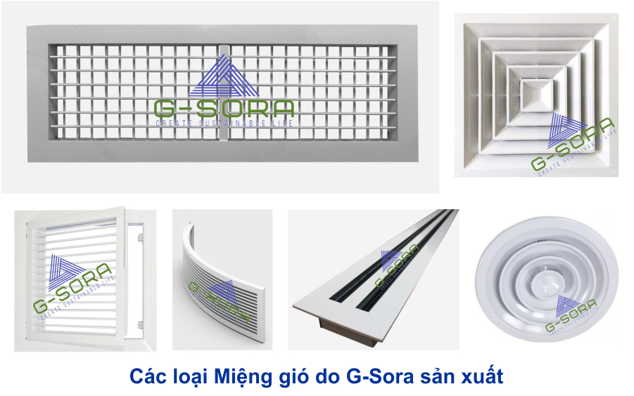
An air diffuser (air terminal or grille) is the terminal device of a heating, ventilation and air-conditioning (HVAC) system that supplies or returns air between the conditioned space and the ductwork. It plays a key role in directing, diffusing and balancing airflow, ensuring air is supplied and returned evenly to maintain thermal comfort.
In a closed HVAC system, cooled or heated air from the indoor unit (AHU, FCU) travels through the supply duct to supply diffusers, which distribute it into the occupied space. After heat exchange, air is drawn back through return grilles for re-treatment or exhaust.
→ The diffuser is therefore the "outlet and inlet" of the entire air exchange cycle.
Diffusers can include adjustable blades, but they do not fully replace the regulating function of a damper.
Diffusers directly affect discharge velocity, noise level and diffusion efficiency. A wrong size or type can lead to:
Understanding diffusers and applying the right type is therefore central to modern HVAC design.
A diffuser consists of several components, each helping to distribute air efficiently, control air direction and minimise pressure loss.
Surfaces are powder-coated or anodised to resist oxidation, limit dust build-up and keep their colour over time.
Blades direct the airflow and can be fixed or adjustable:
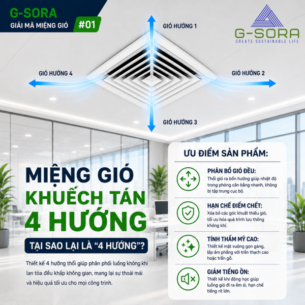
Blade angle and shape determine the throw and spread of the air jet. Multi-directional diffusers spread air more evenly and avoid local cold drafts.
Some diffusers include a coarse dust filter, air distribution cones or stainless insect mesh, which:
Diffusers come in many standard sizes – 150x150, 300x150, 600x600 mm… – depending on duct size and required airflow.
Basic conversion between airflow and free area:
Airflow (m³/h) ≈ Air velocity (m/s) x Free area (m²) x 3600
When sizing, engineers should keep the face velocity below 2.5–3.5 m/s in residential spaces to keep noise low.
Air diffusers work on the principle of forced air supply and return driven by the pressure difference between the ductwork and the conditioned space. When the supply fan pushes air into the system, it reaches the diffuser at a certain velocity; the shape and angle of the blades determine the direction, throw and diffusion.
Blade geometry, free area and face velocity directly affect:
| Stage | Components | Main physical mechanism | Result |
|---|---|---|---|
| Supply | Supply fan, duct, diffuser | Static → velocity pressure, air diffusion | Even air distribution |
| Return | Return grille, return duct | Pressure difference draws air back | Continuous air circulation |
| Pressure relief | Louver / PRD | Opens automatically when pressure exceeds the limit | Zone pressure balance |
The diffuser acts as the "breathing point" of the HVAC system – converting pressure energy into velocity and supplying and returning air in a controlled way. The performance of the whole ventilation system depends heavily on the aerodynamic design and diffusion angle of the diffusers, not only on fan power or duct size.
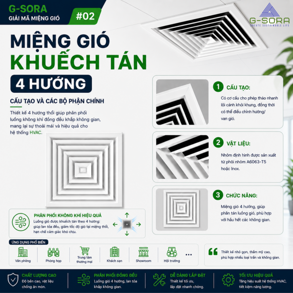
Diffusers are classified by function, construction and installation position to optimise performance and aesthetics.
In short, the diffuser is not a minor accessory but a device that directly affects air distribution, noise and the look of the building. Choosing the right type, size and material determines the performance of the whole system.
As the last element in the air distribution chain, the diffuser directly affects ventilation performance, noise, system pressure and occupant comfort. Diffuser design and selection must therefore follow international and Vietnamese HVAC standards.
Face velocity must be limited to ensure thermal comfort, low noise and effective diffusion. Based on the ASHRAE Handbook and TCVN 5687:2010, recommended values are:
| Area | Max face velocity (m/s) | Permissible noise (dB(A)) |
|---|---|---|
| Bedrooms, hospitals | 1.5 – 2.0 | ≤ 25 |
| Offices, classrooms | 2.0 – 2.5 | ≤ 35 |
| Corridors, public areas | 2.5 – 3.0 | ≤ 40 |
| Factories, warehouses | 3.5 – 5.0 | ≤ 50 |
Design principles:
Diffusers cause pressure loss through changes in air direction, friction on the blades and resistance of screens. The loss is expressed as:
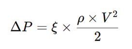
Where:
Example: a supply diffuser with a velocity of 3 m/s and ξ = 0.8:
→ ΔP = 0.8 x 1.2 x 3² / 2 ≈ 4.3 Pa
This loss must be added to the total fan pressure to ensure even distribution.
Technical notes:
Diffusion performance is assessed by how close the air temperature in the occupied zone is to the average supply condition. A diffuser performs well when:
| Standard | Scope | Application |
|---|---|---|
| ASHRAE 55:2020 | Thermal comfort in enclosed spaces | Global |
| ASHRAE 62.1:2019 | Indoor air quality | Global |
| SMACNA Duct Design | Duct and terminal design | HVAC engineers |
| TCVN 5687:2010 | Ventilation and air conditioning – design standard | Vietnam |
| ISO 3744:2010 | Sound power measurement of equipment | Acoustics |
These standards set out velocity, noise, pressure, air direction and temperature limits to ensure performance and comfort.
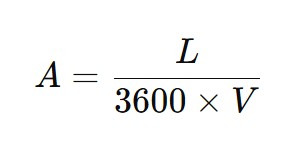
Where: L – airflow (m³/h); V – face velocity (m/s).
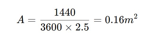
Choose 2 diffusers of 300 x 300 mm (0.09 m² each) → 0.18 m² in total. This meets the velocity and low-noise requirements and distributes air evenly.
→ In professional HVAC design, the diffuser is not just a mechanical part but a factor that directly affects air quality, energy use and comfort.
Depending on the building and comfort requirements, engineers select the diffuser type, position and material to optimise airflow, noise, aesthetics and energy costs.
1. System characteristics:
2. Common diffusers:
| Location | Diffuser type | Purpose | Technical notes |
|---|---|---|---|
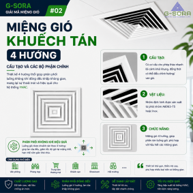
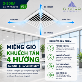
| Living room ceiling | 4-way diffuser | Even cool-air distribution | 45° diffusion, noise ≤ 30 dB(A) |
| Corridor ceiling | Linear slot diffuser | Aesthetics, gentle airflow | Length ≤ 1,200 mm, velocity ≤ 2 m/s |
| Bedroom | 1-way diffuser | Avoid blowing onto the bed | At least 1.5 m from the bed head |
| Wall or ceiling return | Return grille with filter | Collect recirculated air | 0.5–1 m lower than the supply |
3. Layout example: a 25 m² bedroom with 900 m³/h → 2 supply diffusers 250x250 mm (2.5 m/s) and 1 return grille 400x200 mm, ensuring balanced airflow and low noise.
1. System characteristics:
2. Common diffusers:
| Zone | Diffuser type | Face velocity (m/s) | Noise (dB(A)) |
|---|---|---|---|
| Work areas | Square 4-way diffuser | 2.5–3.0 | ≤ 35 |
| Corridors | 1-way parallel-blade grille | 3.0–3.5 | ≤ 40 |
| Closed meeting rooms | Round diffuser | 2.0–2.5 | ≤ 30 |
| Toilets | Ceiling exhaust grille | 2.5–3.0 | ≤ 40 |
3. Technical advice:
4. Layout example: an office of 10 m x 6 m, 3 m high → 180 m³; 12 air changes/hour → 2,160 m³/h. Required free area at 2.5 m/s ≈ 0.24 m² → choose 4 diffusers of 300x300 mm (0.36 m² in total), meeting airflow and noise requirements.
1. System characteristics:
2. Common diffusers:
| Zone | Diffuser type | Material | Feature |
|---|---|---|---|
| Production halls | Adjustable louvred grille | 1.2 mm aluminium or painted steel | Wide air direction adjustment |
| Warehouses | 360° round diffuser or jet nozzle | Stainless steel, aluminium or ABS | Long throw, high pressure |
| Plant rooms | Return grille with filter | Painted steel | Traps dust, easy to clean |
| Service corridors | Pressure relief grille | Aluminium | Balances room and corridor pressure |
3. Design notes:
1. Function: an outdoor louver is used to take in fresh air or discharge exhaust, keep out rain, dust, insects and leaves, and balance pressure between inside and outside.
2. Construction and principle:
3. Materials and applications:
| Material | Application | Notes |
|---|---|---|
| Powder-coated aluminium | External walls, façades | Attractive, lightweight |
| Epoxy-painted steel | Industrial parks | Low cost, mechanically strong |
| 304 stainless steel | Chemical plants, coastal sites | High corrosion resistance |
| Composite | Special projects | Insulating, UV-resistant |
4. Example: a 10-storey building with 8,000 m³/h of fresh-air intake at 3.5 m/s needs about 0.64 m² of free area – arranged as 2 louvers to ensure airflow, avoid noise and improve air exchange.
A complete HVAC system combines:
Layout principles:
Engineers must coordinate airflow calculations, noise criteria, installation positions and diffuser types to achieve the best system performance and occupant experience.
The right air diffuser keeps the HVAC system stable, saves energy and ensures comfort. Selection should be based on airflow, air velocity, noise, building type, material and aesthetics.
Step 1. Determine the supply or return airflow (Q)
Q = A x V x 3600, where Q is airflow (m³/h), A the diffuser free area (m²) and V the face velocity (m/s).
Step 2. Choose a suitable face velocity according to the space type and permissible noise:
| Building type | Diffuser type | Face velocity (m/s) | Airflow per diffuser (m³/h)* | Permissible noise (dB(A)) |
|---|---|---|---|---|
| Homes, villas | 2-way / 4-way supply | 2.0 – 2.5 | 250 – 400 | ≤ 30 |
| Offices, meeting rooms | 4-way diffuser, linear slot | 2.5 – 3.0 | 350 – 600 | ≤ 35 |
| Corridors, restaurants | Single or parallel-blade grille | 3.0 – 3.5 | 400 – 700 | ≤ 40 |
| Warehouses, factories | Louvred / round / nozzle | 4.0 – 5.5 | 700 – 1,200 | ≤ 50 |
| Cleanrooms, plant rooms | Round / HEPA terminal | 2.0 – 2.5 | 200 – 350 | ≤ 30 |
(*Average airflow for a 300x300 mm diffuser)
Step 3. Choose the diffuser type – supply / return / pressure relief; fixed, adjustable or 1–4 way blades; aluminium, steel, stainless steel or engineering plastic.
Step 4. Determine free area and quantity from the airflow and chosen velocity, distributing airflow evenly with minimum noise.
| Building type | Technical requirements | Recommended diffuser | Notes |
|---|---|---|---|
| Villas, townhouses | High aesthetics, quiet, easy to clean | 1–4 way or linear slot diffuser | Concealed in gypsum ceilings, colour-matched to the interior |
| Offices, showrooms | Even, efficient distribution | 4-way, 360° round, parallel-blade return | Combine with temperature and pressure sensors |
| Factories | High airflow and pressure, robust | Adjustable louvred grilles, high-pressure round diffusers | Thick aluminium or epoxy-painted steel |
| Cleanrooms, hospitals | Clean air, positive pressure, dust control | Round terminals with HEPA / coarse filters | Airtight with easy filter replacement |
| Commercial buildings, malls | Optimised airflow and energy | Ceiling diffusers with wall returns | Balance pressure between zones and corridors |
| Parameter | Guidance | Technical limit |
|---|---|---|
| Airflow (m³/h) | Based on cooling load and ventilation needs | Typically 10–15 ACH for offices, 6–8 ACH for homes |
| Face velocity (m/s) | Lower velocity reduces noise in homes | 2–3 m/s (residential), 4–5 m/s (industrial) |
| Noise (dB(A)) | Per ASHRAE 55 and TCVN 5687:2010 | ≤ 35 dB(A) for offices, ≤ 50 dB(A) for factories |
| Location | Ceiling, wall, floor, outdoor | Never blow directly onto people |
| Material | By operating environment | Plastic or stainless in humid areas, aluminium in offices |
| Aesthetics | Slot or concealed diffusers | Matt white or ceiling-matched finish |
| Ceiling height (m) | Recommended diffuser | Diffusion angle | Effective throw (m) |
|---|---|---|---|
| < 2.8 | 1-way or linear slot | 30–45° | 2 – 3 |
| 2.8 – 3.5 | 4-way diffuser | 45° | 3 – 4 |
| 3.5 – 4.5 | 360° round or 2-way | 60° | 4 – 5 |
| > 4.5 | Adjustable louvre / jet nozzle | 60–75° | 5 – 8 |
Engineering tips: low ceilings → 1–2 way diffusers to avoid drafts; high ceilings or large lobbies → round or jet diffusers for long throw and stable airflow.
| Environment | Recommended material | Key properties |
|---|---|---|
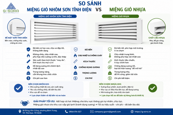
| Indoors (offices, homes) | Anodised / powder-coated aluminium | Light, durable, attractive |
| Outdoors | 304 stainless / epoxy-painted steel | Weather- and corrosion-resistant |
| Chemical and food plants | 316L stainless steel | Acid-resistant, hygienic |
| Cleanrooms / hospitals | White powder-coated aluminium | Easy to clean, dust-resistant |
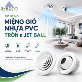
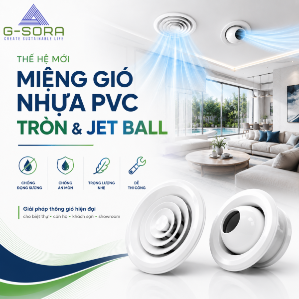
| Humid / cold areas | ABS or PVC plastic | Insulating, rust-free, anti-condensation |

Choose 2 diffusers of 300x300 mm (0.09 m² each): actual velocity ≈ 2.3 m/s and noise < 35 dB(A) – meeting technical and thermal comfort requirements (ASHRAE 55).
A compliant diffuser design must deliver five core technical requirements:
→ Diffuser selection is not just a mechanical exercise but an optimisation of energy, acoustics and aerodynamics across the whole HVAC system.
Installation and maintenance affect not only the finish but also operating performance and airflow balance across the HVAC system. A small error in position or angle can completely change air diffusion, noise and pressure, so installation must strictly follow technical standards.
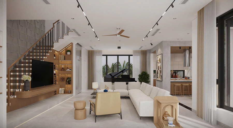
1. Check drawings and specifications
2. Prepare tools and materials
3. Check duct pressure before installation
Step 1. Set out and cut the opening accurately
Step 2. Fit the frame and fix the diffuser
Step 3. Connect to the flexible or main duct
Step 4. Adjust blades and test airflow
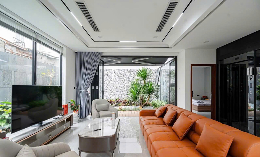
| Check item | Technical criterion | Instrument / record |
|---|---|---|
| Airflow | ±10% of design | Anemometer, flow hood |
| Face velocity | Per ASHRAE tables | Hand-held anemometer |
| Noise | ≤ 35 dB(A) for offices | Sound level meter |
| Air direction | Suits the room layout | Visual check |
| Vibration, leakage | No rattle or leakage | Check joints and gaskets |
| Surface finish | Even coating, no scratches | Visual and light inspection |
Once approved, diffusers should be temporarily covered with protective film until the ceiling is painted.
1. Maintenance intervals:
| Building type | Frequency | Tasks |
|---|---|---|
| Homes, offices | Every 3–6 months | Clean dust, check noise, adjust blades |
| Factories, warehouses | Every 1–3 months | Clean filters, tighten fixings, check leakage |
| Cleanrooms, hospitals | Monthly | Replace HEPA / coarse filters, check pressure differences |
2. Standard cleaning procedure:
3. Maintenance records: log the date, technician, measured noise and airflow after each cleaning. If airflow drops by >15% or noise rises by >5 dB(A), inspect the ducts, dampers or main fan.
| Problem | Cause | Fix |
|---|---|---|
| Uneven airflow | Wrong blade direction or misaligned position | Readjust blades, check throw distance |
| Unusually high noise | Excessive velocity, leakage at the neck | Reduce velocity, seal joints with butyl |
| Condensation on the diffuser | Large temperature difference, poor insulation | Insulate the flexible duct, or use plastic diffusers |
| Peeling paint, oxidation | Humid or acidic environment | Use stainless steel, epoxy coating or plastic |
| Pressure difference between room and corridor | No relief grille or PRD | Add a pressure relief damper or relief louver |
G-SORA supplies air diffusers, dampers and duct accessories in line with SMACNA, ASHRAE and TCVN 5687:2010, meeting the technical requirements of residential and industrial HVAC projects.
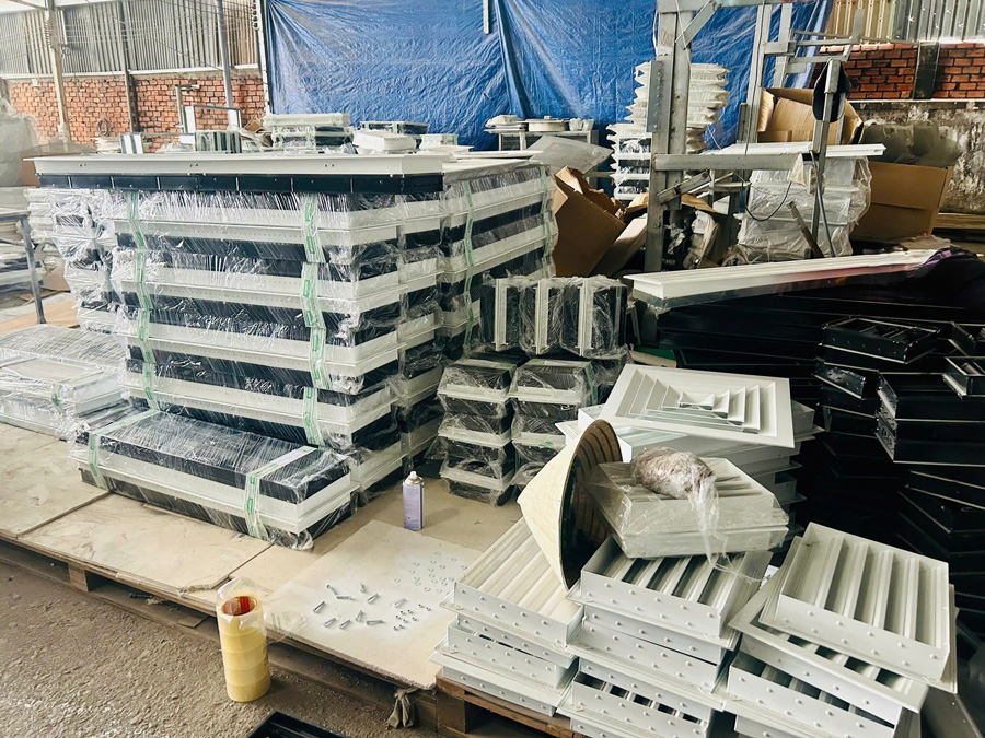
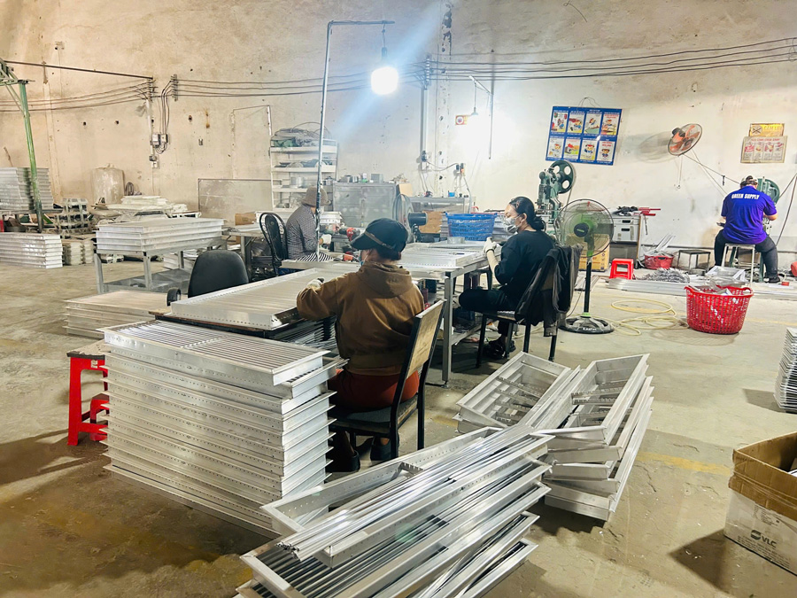
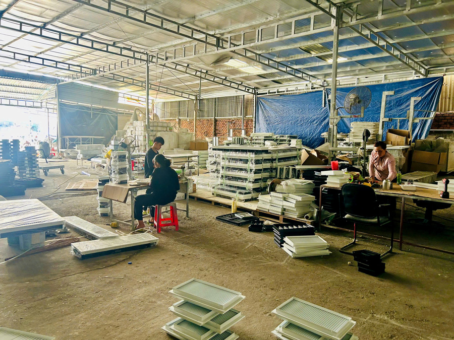
Products are made from 6063-T5 extruded aluminium, powder-coated steel, 304 stainless steel or ABS plastic, using laser cutting, CNC bending and Akzonobel powder coating / anodising for ±0.2 mm accuracy and durable, oxidation-resistant finishes.
Main product lines:
G-SORA provides complete air terminal device solutions for M&E contractors: accurate airflow, low noise, high aesthetics and fast delivery for projects of every size.
Contact G-SORA for advice and the best quotation:
Although the air diffuser is only a small part of the ventilation system, it sits where aerodynamics meets architecture. A good HVAC engineer not only selects the right diffuser but also installs it accurately and maintains it on schedule to keep the system performing efficiently.